A storm is moving across South Florida, and you're watching the roof from a window as gusts hit the house. Shingles lift at the edges, a metal panel flexes, or a membrane balloons for a moment before settling back down. The damage may look random, but wind usually follows a pattern, and roof uplift testing helps determine whether the roof assembly can resist the forces that caused it.
The confusing part is that “uplift testing” doesn't describe one universal procedure. FM 4474, UL 580, UL 1897, ASTM E1592, ASTM E907, and TAS 125 apply to different roof systems and testing situations. A laboratory rating for one assembly also doesn't automatically prove that a different assembly, or an existing installed roof, will perform the same way.
Table of Contents
- Why Roofs Fail When the Wind Picks Up
- What Roof Uplift Testing Actually Does
- The Main Standards That Govern the Test
- Inside a Real Uplift Test From Start to Finish
- When Building Codes Make the Test Mandatory
- Why Field Uplift Testing Is More Complicated Than It Looks
- Reading an Uplift Test Report With Confidence
- Your Practical Checklist Before Repair or Replacement
Why Roofs Fail When the Wind Picks Up
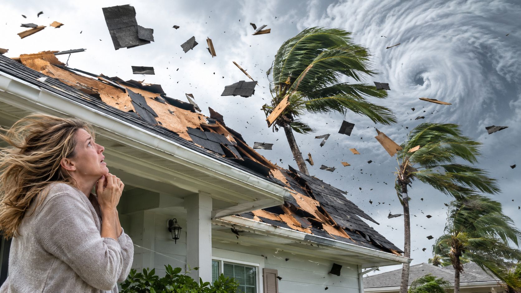
During a South Florida hurricane, bands of strong gusts can pass over a house in quick succession. Wind moves across the roof surface, pressure changes around eaves and overhangs, and air can push upward from below. The roof must resist the resulting force as a connected system, not as a collection of unrelated products.
A roof assembly usually includes the covering, membrane or panels, fasteners or adhesive, insulation, underlayment, decking, and supporting structure. If one layer cannot transfer the force to the next layer, the wind can exploit that weak connection.
Two common failure patterns
Edge failure begins around the perimeter. Wind pressure is often more demanding near roof edges and corners, where airflow changes direction and creates concentrated suction. Fasteners may pull loose, plates may rotate, adhesive may release, or the covering may peel back from the edge.
Field failure affects the broad central area of the roof. A membrane can billow, a panel can disengage from its clips, or a covering can separate over a larger section after the connections have been overstressed.
These failures look different, but both reveal the same principle: the roof's performance depends on the complete assembly. A strong membrane can still fail if the fasteners are poorly spaced. A durable panel can still lift if its clips, seams, or deck connections don't match the tested configuration.
Practical rule: Wind resistance belongs to the roof assembly, not to a product label viewed in isolation.
That's why an inspector doesn't rely only on the name of the membrane, shingle, or metal panel. The deck type, attachment method, fastener pattern, insulation, seams, clips, and roof zone all affect the result. Roof uplift testing recreates those relationships under controlled pressure so a rating has a defined meaning.
What Roof Uplift Testing Actually Does
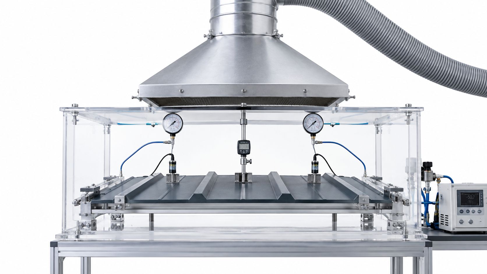
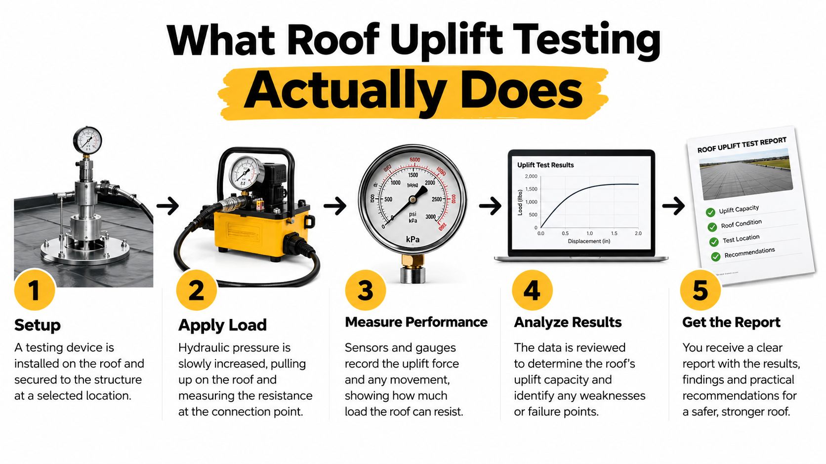
Think of a laboratory test as a controlled tug-of-war. Technicians build a roof section inside a sealed chamber, then create a pressure difference that pulls upward on the assembly. The pressure increases gradually while instruments record how the roof moves and how its connections respond.
The test doesn't merely ask whether a membrane tears. It examines how the full assembly behaves as the force rises.
The basic sequence
Build the specified assembly. Technicians use the stated deck, insulation, cover board, membrane, panels, fasteners, clips, seams, and attachment spacing. A change in any of these details can change the result.
Seal the test area. The perimeter is closed so the chamber can create a controlled pressure differential rather than allowing air to escape freely.
Apply measured pressure. Results are commonly expressed in pounds per square foot, or psf. Pressure is increased in defined steps rather than applied as one sudden blast.
Record movement and connection behavior. Gauges can identify membrane deflection, panel bending, seam movement, fastener loosening, or deck response.
Identify the limiting condition. The test ends when the assembly reaches the target pressure or shows a defined failure. The result describes what that particular configuration resisted.
Why the assembly matters
A product can perform well in one configuration and poorly in another. For example, changing the deck substrate, reducing fastener density, using a different insulation layer, or substituting a clip can alter the load path. The laboratory rating belongs to the tested combination, not automatically to every roof that uses the same top covering.
FM 4474 evaluates roof assemblies under static positive and negative differential pressures. Common test frames include 2 ft × 2 ft, 5 ft × 9 ft, and 12 ft × 24 ft, depending on the roof system and deck substrate, as described in the FM Approvals ANSI/FM 4474 standard.
FM 4474-based ratings are reported in 15-psf increments. Classes such as 60, 75, and 90 indicate resistance levels of 60, 75, and 90 psf maintained for at least 60 seconds. Those figures describe tested uplift resistance, but you still have to compare them with the project's design pressures and the exact assembly description.
The Main Standards That Govern the Test
The right standard depends on the roof system and the question being answered. A laboratory approval for a membrane assembly isn't interchangeable with a field test on an installed roof, and a structural test for standing-seam metal isn't the same as a membrane uplift protocol.
| Standard | Roof System | Test Setting | Result Format |
|---|---|---|---|
| FM 4474 | Built-up, modified bitumen, adhered or mechanically attached single-ply, and other roof assemblies | Laboratory | Pressure resistance in psf and FM class ratings |
| UL 580 | Metal panel roof assemblies and roof deck constructions | Laboratory | UL class or pressure-based assembly result |
| UL 1897 | Roof assemblies requiring incremental uplift verification | Laboratory | Pressure increments, movement observations, and resistance result |
| ASTM E1592 | Standing-seam and through-fastened sheet-metal roof and siding systems | Laboratory | Structural response under uniform static pressure |
| ASTM E907 | Adhered membrane roofing systems installed over different substrates | Field | Pressure intervals and observed uplift or deflection response |
| TAS 125 | Metal roofing systems in Florida compliance pathways | Typically project or jurisdiction-specific testing | Florida approval and compliance documentation |
What each standard tells you
FM 4474 became a formal consensus-based industry practice for evaluating simulated wind uplift resistance using static positive or negative differential pressure. FM 4470 ties certification to those results, with Class 1-60 as the minimum rating required for certification and Class 1-990 as the maximum available rating, according to the FM standard.
UL 580 and UL 1897 address roof assembly uplift through incrementally increased static pressure. UL 1897 uses 15 psf increments held for at least one minute, while recording vertical movement throughout the progression.
ASTM E1592 focuses on the structural behavior of sheet-metal roof and siding systems under uniform static air pressure. It's particularly important for standing-seam systems because panel bending, seam integrity, clip performance, and support spacing influence the result.
ASTM E907 is a field method for adhered membrane roofs. It can apply pressure in 15 psf intervals up to the calculated design wind uplift pressure, making the test project-specific rather than a generic product check.
For Florida property decisions, a homeowner may also benefit from broader guidance on how storm openings and roof systems work together, such as this coastal window guide from Black Badge Doors. It doesn't replace roof engineering, but it helps explain why the building envelope must be considered as a connected system.
Inside a Real Uplift Test From Start to Finish
A technician begins with the assembly description, not the pressure gauge. The report should identify the deck, insulation, membrane or panel, fasteners, clips, adhesive, seam profile, and spacing. If the built specimen doesn't match the proposed installation, the resulting rating won't answer the project's actual question.
How the laboratory run proceeds
The selected roof section is mounted inside a sealed pressure chamber. Technicians seal the perimeter, check the equipment, and calibrate pressure transducers and deflection gauges before applying load.
The chamber then increases suction in equal, controlled increments. Each increment is held for a defined dwell period while gauges record movement at important locations, including the deck, seams, membrane surface, fasteners, and plates.
Failure often develops progressively. The first warning may be fastener back-out, seam peel, fastener-plate rotation, membrane billowing, or movement that doesn't recover after pressure is reduced. A dramatic tear can happen, but it isn't the only meaningful failure condition.

The technician compares the readings with the governing procedure and checks for chamber leakage. Pressure measurements may require correction so the report reflects the pressure acting on the specimen rather than pressure lost through the test setup.
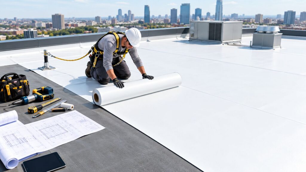
The run ends at the target pressure or at the first defined observable failure. A report should show the pressure sequence, hold times, observations, deflection data, corrections, and final rating. A useful visual reference for commercial roof work is this commercial roof installation image, especially when discussing how the approved test assembly must match field installation details.
When Building Codes Make the Test Mandatory
Building codes and approval systems use uplift testing to connect wind design with roof construction. The required resistance varies across the roof because wind exposure isn't uniform. The field, perimeter, and corner zones can require different design pressures on the same building.
IIBEC notes that code Section 1504.3.1 identifies built-up, modified bitumen, fully adhered or mechanically attached single-ply systems, metal panel roofs on solid or closely fitted decks, and other membrane coverings for testing under FM 4474, UL 580, or UL 1897. The governing code pathway depends on the roof type, deck, attachment method, jurisdiction, and project conditions.
Roof zones change the required rating
The field is the broad interior portion of the roof. The perimeter is closer to edges, while corners experience especially concentrated wind effects. A roof rating that satisfies the field may not satisfy the perimeter or corner requirement.
The verified design examples below show how zone-specific pressures can differ:
| Design Wind Speed | Field Zone (psf) | Perimeter Zone (psf) | Corner Zone (psf) |
|---|---|---|---|
| Not specified in the verified example | 45.12 | 70.82 | 96.52 |
These values come from an industry design example rather than a universal rule. The actual pressures for a property must come from the project's wind design, building geometry, exposure, importance, and applicable code.
Where testing enters the project
Testing and approved assemblies may become relevant during new construction, reroofing in high-wind regions, insurance review after a major storm, and warranty compliance for mechanically attached or adhered systems. In Florida's High Velocity Hurricane Zone, including Miami-Dade and Broward, local approval requirements can add another layer to the documentation.
A Class 60 assembly may be adequate for one roof zone and inadequate for another. That's why an inspector should compare the report with the pressure schedule rather than treating the class number as a universal pass.
Property owners reviewing storm coverage can also use this resource to compare windstorm policies in Tampa Bay. Insurance requirements vary, so the policy should be read alongside the roof's inspection and compliance documents.
Why Field Uplift Testing Is More Complicated Than It Looks
A portable vacuum rig can provide useful information, but a localized field test doesn't automatically reveal the full design capacity of an entire roof. The rig applies pressure to a limited area, and the result may be controlled by the weakest nearby fastener, plate, seam, adhesive bond, or substrate condition.
That difference matters after a storm or reroofing project. A single test point can produce a result that reflects local moisture, temperature, prior damage, installation variation, or rig geometry rather than the performance of every roof zone.
The disagreement over acceptance testing
The National Roofing Contractors Association has stated that field uplift testing is inappropriate for post-installation quality assurance because results can vary and correlate weakly with laboratory uplift testing. That position doesn't mean field methods have no value. It means the test result needs careful interpretation and shouldn't automatically become a simple pass/fail verdict for the finished roof.
ASTM reinstated ASTM E907-25 in January 2026, keeping the field method relevant while also highlighting the need to understand its limits. FM Global's updated field-verification guidance reduced the recommended field-test safety factor from 1.5 to 1.25, showing that the conservatism applied to field results has been actively recalibrated. These details are documented in this discussion of field uplift testing and verification guidance.
What a field result can and can't prove
ASTM E907 applies to adhered membrane roofs with any substrate type, including assemblies with or without mechanically fastened or adhered cover board, rigid board insulation, or base ply. Under that procedure, a roof can be tested up to the calculated design uplift pressure, but the interpretation still depends on deflection and the exact assembly.
FM 1-52 uses a different sequence. It starts at 15 psf and rises in 7.5 psf increments up to 1.25 times the design uplift pressure. ASTM E907 and FM 1-52 can therefore produce different interpretations for the same roof, particularly when movement becomes significant.
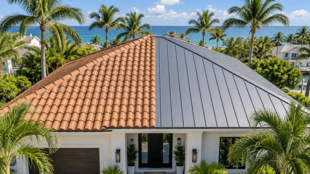
A field test is one piece of evidence. It shouldn't replace a complete inspection of seams, fasteners, flashings, substrates, moisture, and roof-zone requirements. This roof comparison image can help frame the larger repair discussion, but the test standard and assembly details must drive the technical conclusion.
Reading an Uplift Test Report With Confidence
A report should answer a practical question: does the tested assembly provide the resistance required for this building, in this roof zone, under the applicable standard? Start with the assembly description because the number on the final page has little value if the specimen doesn't match the roof being evaluated.
Read the assembly before the rating
Look for:
- Deck type: Confirm whether the test used the same structural deck or substrate.
- Attachment method: Check fasteners, adhesive, clips, plates, and seam details.
- Spacing and pattern: Verify that fastener and clip spacing match the installation.
- Insulation and cover board: Substitutions can change load transfer.
- Membrane or panel profile: The same product family may have different tested configurations.
Next, review the pressure table. Identify the field, perimeter, and corner requirements, then compare each one with the test result. Check whether the stated pressure is the applied test pressure, a design pressure after a safety factor, or a classification label.
Understand movement, not only pressure
Deflection readings show how much the assembly moved under load. A temporary movement that returns to its original position may have a different meaning from permanent deformation, connection slip, or progressive separation. The report should also identify whether the pressure was held for the required time or merely reached momentarily.
| Rating / Class | Test Standard | Typical Design Pressure (psf) | Common Implication |
|---|---|---|---|
| Class 60 | FM 4474-based reporting | 60 | May address a lower required zone, but must be compared with the project schedule |
| Class 75 | FM 4474-based reporting | 75 | Provides a higher tested resistance than Class 60 |
| Class 90 | FM 4474-based reporting | 90 | May satisfy a demanding zone when the assembly and design pressure align |
| FM 1-90 | FM-rated assembly designation | 90 | Indicates a 90-psf class designation, subject to the complete approval and project requirements |
FM 4474 ratings use 15-psf increments, and classes such as 60, 75, and 90 describe resistance maintained for at least 60 seconds under the applicable procedure. A rating can support code compliance, insurance review, or warranty documentation only when the roof assembly and required zone match the approval.
If the report falls short in one zone, the answer might involve a localized repair, a recover system, or full replacement. The report alone doesn't decide that. An inspector must connect the pressure result with roof condition, moisture, attachment quality, and the feasibility of bringing the entire assembly into compliance.
Your Practical Checklist Before Repair or Replacement
When someone recommends roof uplift testing, ask for the reason in plain language. Are they verifying a proposed new assembly, investigating storm damage, reviewing an existing roof, or trying to satisfy an insurer or code official? The answer determines whether a laboratory approval, engineering review, or carefully interpreted field method is appropriate.
Before the test
- Confirm the standard: Identify whether the roof calls for FM 4474, UL 580, UL 1897, ASTM E1592, ASTM E907, TAS 125, or another governing pathway.
- Match the assembly: Request the deck, membrane or panel, insulation, fastener pattern, clip details, seam profile, and attachment method in writing.
- Check the facility: Ask whether the laboratory or testing organization has the qualifications and accreditation required for the project.
- Record the roof condition: Photograph seams, edges, fasteners, flashings, penetrations, damaged areas, and visible moisture before work begins.
During and after the test
Attend if practical, or ask for photographs and raw records. Save the pressure sequence, hold times, deflection readings, failure observations, leakage corrections, and final report, not only the summary page.
Then compare the rating with every roof zone. A system that satisfies the field pressure may still need additional work at the perimeter or corners. Check that the safety factor used in the report is current and that the tested configuration matches what the contractor installed.
The repair decision should reflect the evidence:
- Spot repair: Appropriate only when the surrounding assembly remains sound and the documented weakness is localized.
- Recover: Possible when the existing roof and substrate support an approved new assembly.
- Full tear-off: More likely when moisture, widespread attachment failure, incompatible layers, or zone-wide deficiencies prevent a reliable recover.
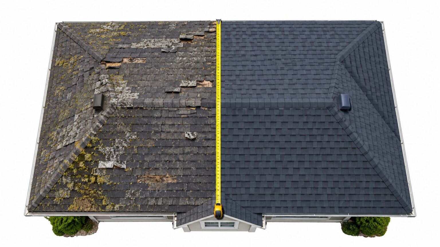
Keep the final report with permits, product approvals, invoices, photographs, maintenance records, and insurance correspondence. This roof repair or replacement comparison can help organize the larger decision, but the uplift report and local requirements should control the technical evaluation.
Paletz Roofing and Inspections can assess roof condition, review uplift-related documentation, and connect the test result with repair or replacement options for properties in South Florida. Visit Paletz Roofing and Inspections to schedule an inspection or request guidance before approving roofing work.